A Tourist's Guide to JPEG
Posted Nov 26, 2023
Tags: compression, image processing, standard, javascript
Before the cloud, small file sizes meant you could stuff more in your pockets. And so, JPEG and MP3 were two extensions that I paid attention to when I was younger.
College gave me a reasonable idea of how compression standards like JPEG actually cut down on information without doing too much damage to perceptual quality. It was a great mathematical exercise, but it left me wondering how the bytes actually get sent down the wire. Having spent more time in the tech industry looking at a myriad of other file transmission standards (HTTP, HLS, WebRTC) and opening up media files (.aac, .mp4), I knew that JPEG had to have a similar layer of standardization to help with the logistics of assembling and disassembling an image. This blog post is about that.
It must be stated that this post isn’t an exercise in building a fully-featured JPEG decoder or even a rigorous study of the JPEG standard. In the last few weeks, what started as a quest for a bite-sized project for me to do in Rust as a matter of getting good at it turned into the study of the media standard and its decoders. I proceeded to write the rest of the parser in Javascript instead. My goal was to dive head first into inspecting binaries, and use the spec and publicly available decoder implementations as a reference to understand how all the pieces are arranged.
If anything, this is more like an unboxing video that spends more time studying the packaging rather than the actual contents; or a tourist vlog that unravels a city through its subjective observations and sights. And thus, I will gloss over some of the core aspects of JPEG image encoding, namely DCTs, quantization and entropy (Huffman) coding. These concepts are better explained elsewhere – and heavily documented in several textbooks and open source implementations.
Diving In
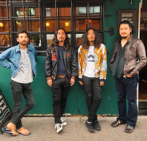
I picked an arbitrary image from the eldritch nightmare that is my Downloads folder.
After loading it into memory with a fetch(), I read it as an array buffer. It began with an ffd8. Quickly looking through the spec, ffd8 and ffd9 are Start- and End-of-Image markers respectively. These are presumably useful in detecting if a file is complete after being passed around on a network. Kinda like brake vans bookending a train.
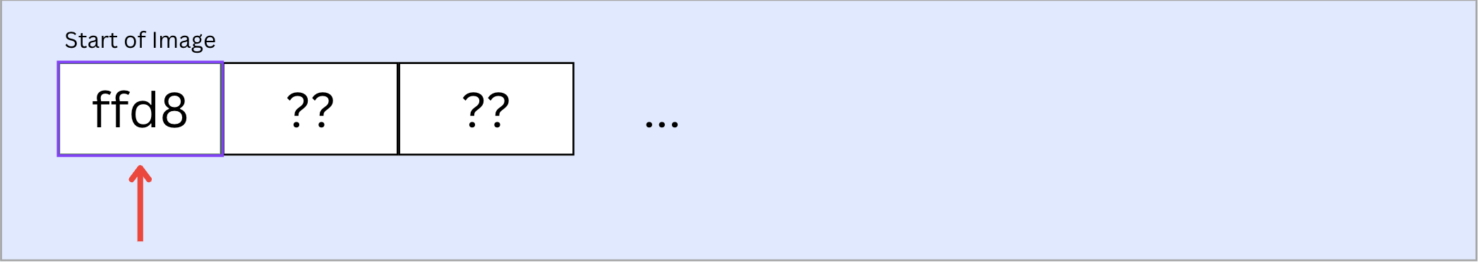
At this point, it might help to quickly understand what Markers even are: JPEG files, while representing 2D information, are still stored as a stream of bits. This stream is divided into Segments, each containing a meaningful chunk of data that can be processed on its own to glean information. Each segment has a Marker at its head, which tells you what type of a segment it is, followed by Length, and the actual contents of the segment. Length is used by the decoder to calculate where a given segment ends and the next starts.
~/Documents/dev/jpeg-parser > node main.js
Debugger attached.
<Buffer ff d8 ff e0 00 10 4a 46 49 46 00 01 01 00 00 48 00 48 00 00 ff e1 00 8c 45 78 69 66 00 00 4d 4d 00 2a 00 00 00 08 00 05 01 12 00 03 00 00 00 01 00 01 ... 50563 more bytes>
## first marker (SOI) ffd8
## next marker (APP0): ffe0
The second marker is ffe0. ffe0 → ffef are Reserved for Application Segments.
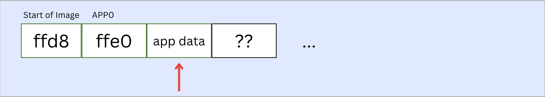
It’s unclear what Application Segments are truly meant for. But it appears that they are not strictly necessary according to the JPEG standard. They are often used by cameras and other applications to insert data. APP0 is specifically used to insert thumbnail images and camera configuration.
The bytes following ffe0 in this marker are 0010, which is the number of bytes of data in this segment i.e. 16. The length byte always includes itself in the length measurement, so the actual length of data is length - 2; in this case 14 bytes.
The following bits 4a 46 49 46 00 appear to be a file signature. Searching around for this hex string led me to the conclusion that it is a hard coded signature for a JPEG / JFIF file. The rest of this segment is mostly JFIF metadata that comes with the file that I needed to parse through based on byte positions.
## first marker (SOI) ffd8
## next marker (APP0): ffe0
## JFIF metadata {
  version: { major: 1, minor: 1 },
  densityUnits: 0,
  xDensity: 72,
  yDensity: 72,
  thumbnailW: 0,
  thumbnailH: 0,
  thumbnailData: <Buffer >
}
This was followed by ffed. Another application segment. I couldn’t find much information on what this is about. But given it’s an application segment, I chose to ignore whatever it is, and move on.
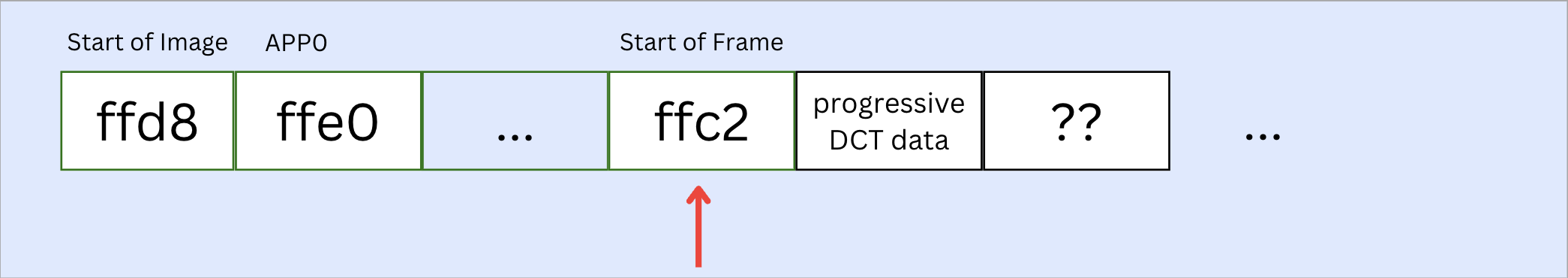
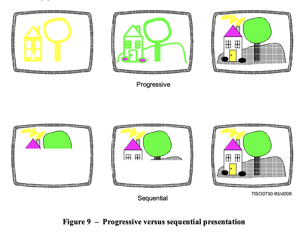
The next segment was ffc2. Looking through the standard, this is a Start Of Frame (SOF) segment. A Frame is a collection of scans dedicated to image-related data. An SOF segment contains metadata about the frame that follows. This specific SOF is an SOF2, which means that the frame is coded in Progressive DCT mode. Progressive DCT?
JPEG has 4 types of coding “modes” – sequential DCT, progressive DCT, lossless and hierarchical. Sequential and progressive DCT modes follow the same steps but are sequenced differently: In case of Sequential DCT, the encoder selects 8*8 blocks in the image, applies DCT, and then proceeds to quantize and entropy-code them in the order of processing i.e. successive blocks left-to-right on each row, and then top to bottom rows. This means that when the image is decoded, each block can be decoded separately, and hence the image would be presented in in the same order of encoding.
In case of progressive DCT, once the blocks have been processed via DCT, instead of moving in a sequential fashion, the encoder does several passes on the entire image. During each pass, it only encodes the most significant DCT coefficients from each block, adding more and more details in successive blocks. This way, when decoding, the entire image can first be obtained in low detail, with details in subsequent steps.
 (Source: JPEG standard)
The number of components in a frame is encoded in a byte immediately following the frame header. Our frame contains 3 components. My assumption is that this refers to JPEG image components (Y, Cb and Cr) for color information. We can now iterate on these components to see what is in them.
Each component has a component id, horizontal (h) and vertical (v) sampling factors, and a ‘quantization table destination selector’ (Q). Q specifies one out of four possible quantization table destinations, from which the table can be used for de-quantization of DCT coefficients in the current component. The actual quantization table will be saved to this destination for us when it’s obtained, in time for the decoding of scans. If a component is split across several scans (as would be the case with our progressive DCT image), this one table destination will apply to all of them.
With this knowledge, we can look through these components and read blocks of data in this frame. The start-of-frame segment also typically offers information on the number of blocks, and their dimensions. This can be used to allocate memory (define some empty arrays in our case) to then store data into whenever we get to decoding.
  components: {
    '1': {
      h: 2,
      v: 2,
      quantizationIdx: 0,
      blocksPerLine: 63,
      blocksPerColumn: 61,
      blocks: [Array]
    },
    '2': {
      h: 1,
      v: 1,
      quantizationIdx: 1,
      blocksPerLine: 32,
      blocksPerColumn: 31,
      blocks: [Array]
    },
    '3': {
      h: 1,
      v: 1,
      quantizationIdx: 1,
      blocksPerLine: 32,
      blocksPerColumn: 31,
      blocks: [Array]
    }
  },
  componentsOrder: [ 1, 2, 3 ],
  maxH: 2,
  maxV: 2,
  mcusPerLine: 32,
  mcusPerColumn: 31
(Note in the code above that components 2 and 3 i.e. Cb and Cr have smaller dimensions. This is because JPEG quantizes chroma components more aggressively than the luma component in order to maintain perceptual quality while reducing bytes)
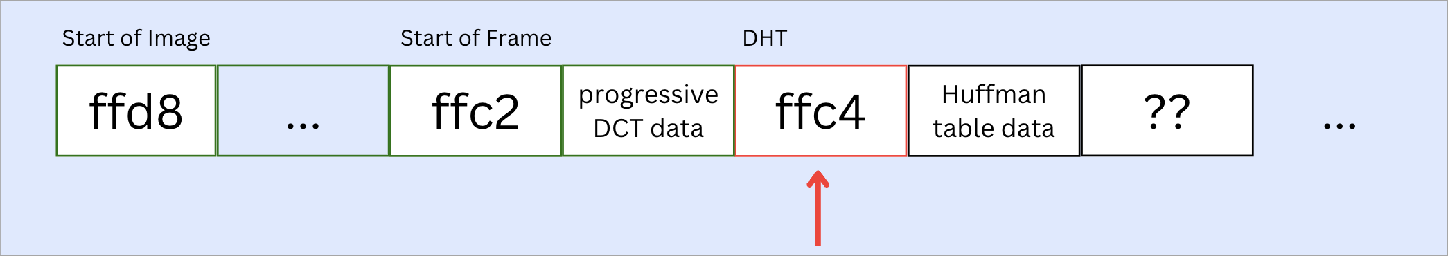
Our next segment came with a ffc4 marker, which signifies a Define Huffman Table(s) (DHT) segment. This segment offers a map of Huffman codes to their corresponding values, which we can then use to derive DCT values while decoding image data. I will not get into huffman coding here, but the tl;dr is that it creates a morse-code like map that assigns smaller byte strings to more frequently occurring values. This reduces the overall number of bits used to represent a given amount of data. In order to retrieve the source data, you would still need the original map, which is what a Huffman Table is.
After parsing and building a table, I had to repeat this a few more times. It is possible that the Huffman Table is split across multiple segments (though apparently, the opposite is also true: several tables can be in one segment). I found 4 DHT segments.
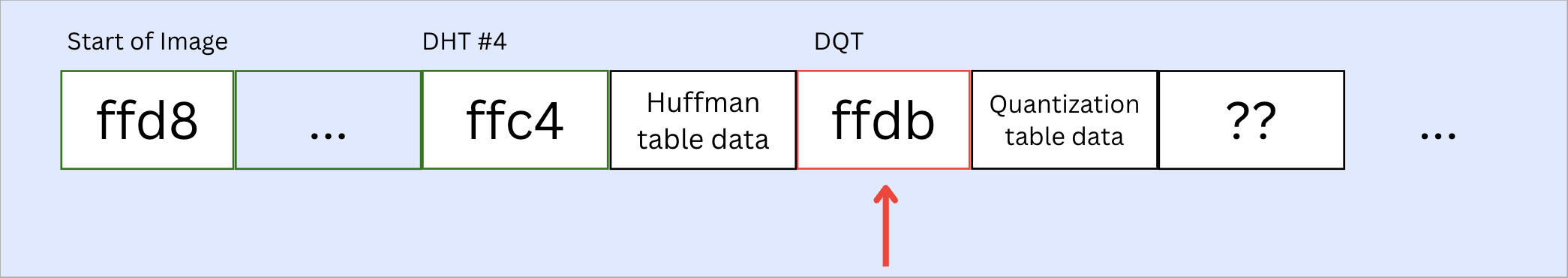
The next segment came with a ffdb marker, which signifies a Define Quantization Table. This table contains definitions for one or more quantization tables.
This segment also contains a Precision property, which can either point to 8 or 16-bit precision. For our image, it’s 8-bit. The destination for this table is 0. There were two such segments.
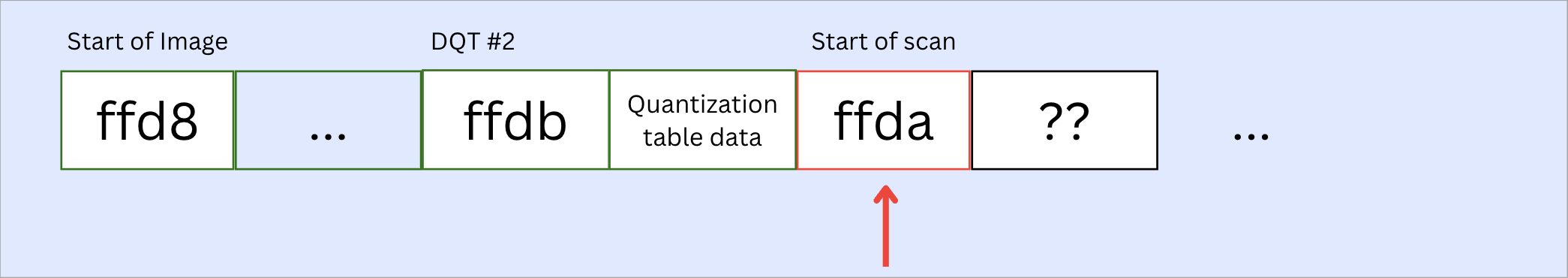
The next segment came with the marker ffda, which is a Start Of Scan marker. The Start Of Scan segment specifies specifies which component(s) are contained in the scan that follows, the destinations from which the entropy (Huffman) tables to be used with each component are retrieved, and for progressive DCT, which part of the DCT quantized coefficient data is contained in the scan. A scan can contain several entropy coded segments (ECS), each of which can contain multiple units of data, referred to as Minimum Coded Unit (MCU). As the name suggests, MCUs are the atomic unit of information in a JPEG file.
I also found some notes in the standard about interleaved components, but as far as I can tell it only applies to sequential mode. When not interleaved, the entropy coder encodes all coefficients from one component before moving on the next one. In case of non-interleaved components, MCU would be 1.
I patched together a decoder with borrowed code with the intention of moving on. After 5 scan segments, there was another DHT segment followed by 2 scans. And then another DHT. And then 3 more scans.
Then, I found an ffd9 segment, signifying End Of Image.
This is the end of the array buffer. From this image, we got 6 Huffman table, 2 quantization table and 10 scan segments containing encoded image data. All of the scans have already been decoded and organized into components within a frame (I copied some Huffman decoding logic from elsewhere to achieve this). All that’s left to do is to dequantize the components, apply Inverse-DCT to get actual pixel values, and position them appropriately in the image frame. This set of steps is inherently mathematical and less a function of file standards. I wasn’t interested in this part anyway, so we will stop here.
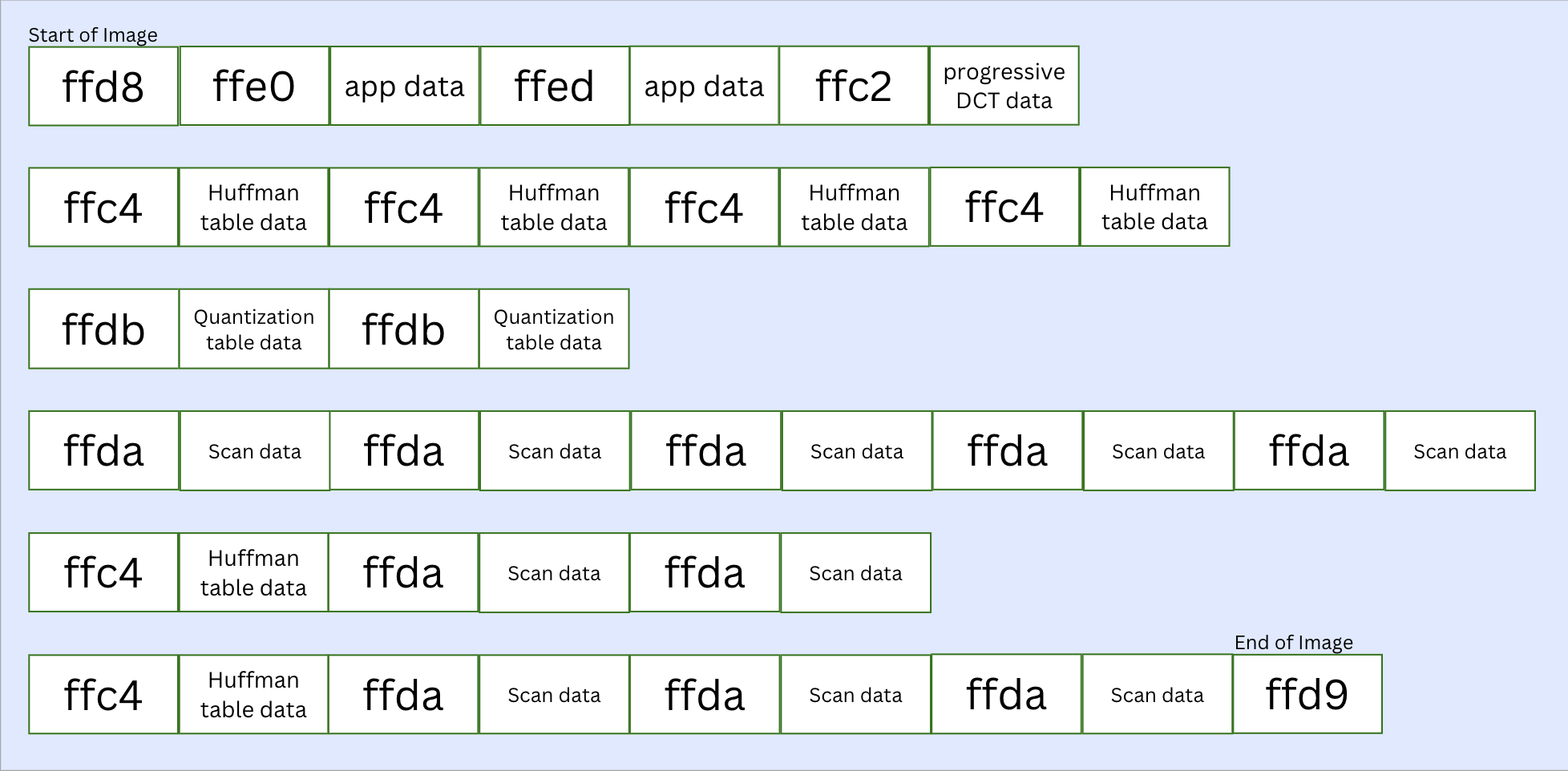 (All the parsed segments from the image; individual ECS within scans have been truncated into “scan data” for brevity)
Observations
-
This whole exercise left me feeling like I’d formed a hybrid Turing machine with my computer: we read binary information piecewise from a stream, and each new byte gave us new information on where we were, and what to do with the next n bytes coming up. This is a new way for me to interact with complex data on a computer. I’ve done this with strings and small arrays, but never at this scale.
-
Flipping through the JPEG spec and various implementations gave me a feel for how the standard itself is declarative, with implementations being given a lot of freedom in terms of how they approach the actual encoding/decoding of data. My own program in its current form was written in a heavily procedural way, and would likely not work with anything besides my test image.
-
This is likely my first interaction with nesting information from a flattened array outside of a leetcode exercise. While the standard goes into detail about the hierarchical structure of segments, it’s fascinating to see everything inevitably get flattened out as a byte stream, with markers signifying starts and ends.
-
I’ve developed a newfound appreciation for how fast all of this happens on a computer. Despite all the compression, parsing through a JPEG is a laborious process and makes me very conscious of the Kolmogorov-esque tradeoffs involved in compressing data i.e., at what point does the transmission of instructions to reconstruct data become less efficient than the transmission of data itself?
At the end of it all, I am intrigued and a bit underwhelmed. While I built a parser to wade through all the packaging around the image, this exercise didn't give me the gratification of painting pixels on a screen. Maybe I will attempt writing de-quantization and inverse-DCT logic sometime soon after all — for closure, if nothing else.
Links
- JPEG Standard – https://www.w3.org/Graphics/JPEG/itu-t81.pdf
- EXIF description format doc – https://www.media.mit.edu/pia/Research/deepview/exif.html
- A corpus of file signatures – https://www.garykessler.net/library/file_sigs.html
- A handrolled JPEG decoder in Rust – https://github.com/martinhath/jpeg-rust/blob/master/src/jpeg/decoder.rs